8086 Microprocessor Architecture, Features, and Pin Diagram
Introduction
In this article, I am going to explain about 8086 microprocessor Architecture, features, and Pin Diagram of 8086 Microprocessor. This microprocessor is regarded as the first member of the x86 family. It is an 8-bit/16-bit microprocessor, introduced by Intel in the late 1970s. The 8086 Microprocessor Architecture was defined by Stephen P. Morse. The Architecture of the 8086 Microprocessor is divided into two parts, the Bus Interfacing Unit and the Execution Unit. let’s discuss the detailed architecture of the 8086 Microprocessor further.

8086 Microprocessor Architecture
8086 Microprocessor is an advanced version of the Intel 8085 Microprocessor. it has a record of the most successful line of microprocessors among Intel’s processors. As mentioned earlier the 8086 Microprocessor Architecture is divided into two parts, BIU(BUS Interfacing Unit) and EU(Execution Unit).
- Bus Interfacing Unit(BIU)
- Execution Unit(EU)
1-Bus Interfacing Unit(BIU)
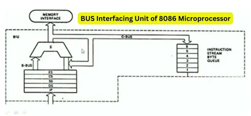
The Bus Interfacing Unit is responsible for communicating between external devices and peripherals including memory via a system bus. the main purpose of BIU is fetching the instructions from memory, reading and writing data from Input/output ports, and memory as well. it also provides an address relocation facility. the bus interfacing unit has three parts Segment Registers, Instruction Queue, and Instruction Pointer.
(a)-Instruction Queue
the bus interfacing unit(BIU) prefetches six instruction bytes in advance from memory. these prefetch instructions are stored in a group of high-speed registers known as the instruction queue. this instruction queue works on FIFO order. the BIU(Bus interfacing unit) works in parallel with the execution unit(EU). The BIU fetches the instruction bytes while the EU is executing an instruction. the simultaneous operations of BIU and EU are possible only when the EU does not require the system bus. the process of fetching the next instruction in advance while the EU is executing the current instruction is known as pipelining.
(b)-Segment Registers
the 8086 microprocessor architecture has the capability of addressing 1 MB of memory, which is divided into 16 logical segments. each segment contains 64K bytes of memory, but at any given time 8086 works with only four 64 kb segments. each segment associated with the segment register and they are given below.
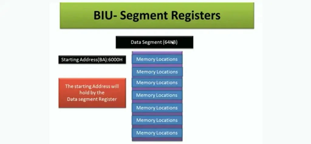
- Code Segment(CS) Register-16 bit
- Data Segment(DS) Register-16 bit
- Stack Segment(SS) Register-16 bit
- Extra Segment(ES) Register-16 bit
these registers are used to store the upper 16 bits of the starting address (known as the base address) of four memory segments. bus interfacing unit generates the 20-bit address using the segment and offsets components(the effective address) of an address.
(c)-Instruction Pointer
the instruction pointer holds the address of the next instruction which is to be executed next. it contains the offset value (effective address) of the next instruction.
2-Execution Unit(EU)
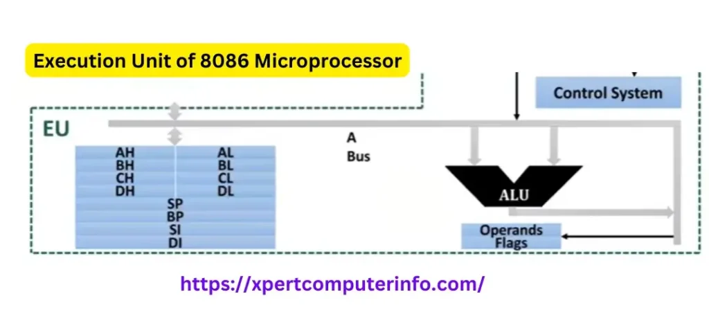
the execution unit(EU) informs the BIU From where the instruction or data is to be fetched. the execution unit performs the following functions:
- It picks up the instruction from the instruction queue of the Bus interfacing unit(BIU).
- It decodes the instructions and then executes the instructions.
- It updates the status of the flag register.
(a)-EU-Control Unit
EU-Control Unit is responsible for controlling and coordinating all activities performed by various sub-units. this unit fetches the instructions from the instruction queue, decodes the instructions, and executes the instructions. this control unit also issues various control signals such as reading/ writing data etc, to perform various operations.
(b)-EU-Arithmetic Logic Unit
it performs all arithmetic and logical operations, and results may be stored temporarily in general-purpose registers or index registers.
(c)-EU-General Purpose Registers
the registers such as AX, BX, CX, and DX Are called general-purpose registers. these registers are used to store the data temporarily. the data can be accessed very fast by these registers.
(d)-Pointer and Index Registers
Pointer and index registers are used normally to get the data from memory or write the data into memory. the pointer registers are BP, SP, and IP. The index registers are SI and DI.
(e)-Flag Registers
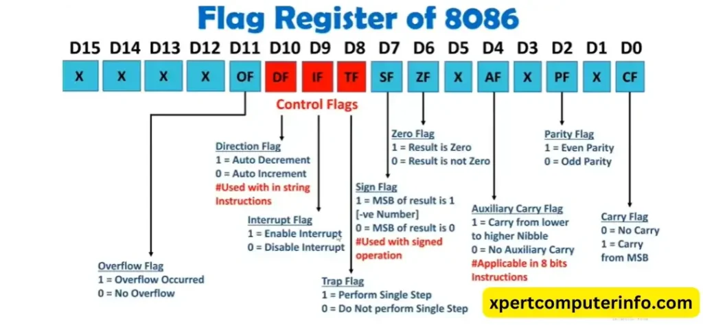
the 8086 Microprocessor Architecture contains a flag register which is a combination of 16 flip-flops that can be individually set or reset accordingly after executing the instruction which can be used to control the various operations of the execution unit.
8086 Microprocessor Addressing Modes
How the operands(Data) are accessed by instruction is called an addressing Mode.

the different addressing modes of 8086 Microprocessors are given and explained further:
- Immediate Addressing Mode
- Direct Addressing Mode
- Implied/ Implicit Addressing Mode
- Indirect Addressing Mode
- Based Addressing Mode
- Indexed Addressing Mode
- Based Relative Addressing Mode
- Indexed Relative Addressing Mode
1-Immediate Addressing Mode
In this addressing mode, the data (1 byte/2 bytes) specified in the instruction is directly transferred into the register.
2-Register Addressing Mode
In Register Addressing Mode operands are specified in registers only.
3-Direct Addressing Mode
In this mode address of the operand is specified in the instruction.
4-Implied/ Implicit Addressing Mode
in this kind of Addressing Mode, the operand is implied in the instruction.
5-Indirect Addressing Mode
The address of the Operand is stored in the registers. in the 8086 Microprocessor Architecture, indirect addressing mode have further modes categories:
- Register Indirect Addressing Mode
- Register Relative Addressing Mode
- Base Indexed Addressing Mode
- Based Indexed Relative Addressing Mode
1-Register Indirect Addressing Mode
in this addressing mode, the operand address will be given by a memory pointer.
2-Register Relative Addressing Mode
In this addressing Mode, The operand address will be given by the Memory Pointer with 8-bit or 16-bit displacement.
3-Base Indexed Addressing Mode
In this addressing Mode, the operand address will be given by base register and index register.
4-Based Indexed Relative Addressing Mode
In this addressing Mode, the operand address will be given by the base register, index register with 8-bit or 16-bit displacement.
Assembler Directives in 8086 Microprocessor Architecture
Assembler directives are also called pseudo-opcodes. These are not instructions, so they are not executed by MPU. These are used to define Integers, Characters, Strings, and Segments, etc.
Pin Diagram of 8086 Microprocessor Architecture
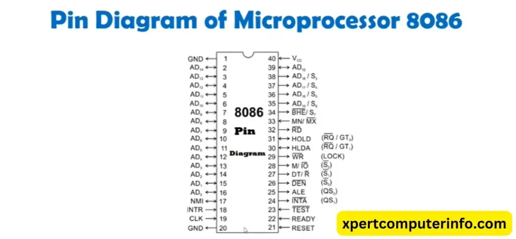
Address Data Bus[AD0-AD15]
- 8086 Microprocessor has 20 lines for the address bus and 16 data lines.
- Here, AD0-AD15 are time multiplexed address data lines and can be separated by ALE Terminal.
- If ALE=1, then it carries address [A0-A15], and if ALE=0, then it carries data [D0-D15].
Address Status Lines-[A19/S6-A16/S3]
- 8086 has 4 time multiplexed address status lines A19/S16-A16/S3 and can be separated by ALE terminal.
- If ALE=1, then it carries address(A-19-A16), and if ALE=0, then it carries status signals(S6-S3).
Status Signals [S7/S3]
- S3 and S4 indicate which segment is accessed by the 8086 Microprocessor during the current bus cycle.
- S5 reflects IF Flag register.
- S6 is always zero.
- S7 is always one.
BUS High Enable(BHE/S7)
- This line is used to enable D15-D8 of D15-D0.
- It is used by Microprocessor for Memory Banking.
Non Maskable Interrupt(NMI)
- This line is used to give the highest-priority interrupt to the 8086 Microprocessor.
- It can not be disabled by the software.
- It is a positive edge-triggered interrupt.
- When it occurs, a type 2 interrupt occurs in the 8086 Microprocessor.
Interrupt Request(INTR)
- This is level triggered hardware interrupt.
- It depends on the status of the Interrupt flag.
- If “IF=1” and “INTR=1”, the 8086 Processor gets interrupted.
- If “IF=0” and “INTR=1”, then INTR is disabled.
Interrupt Acknowledgement(INTA)
- Along with the Interrupt request on INTR, Microprocessor gives Interrupt Acknowledgement to the peripherals.
System Clock(CLK)
- The clock is given to the 8086 for internal timing.
- The clock with 8086 is 5MHZ, 8MHZ and 10 MHZ respectively.
Minimum and Maximum Mode(MN/MX)
- For Minimum Mode connected with Vcc.
- With Minimum Mode, 8086 will work as the single microprocessor.
- For Maximum Mode connected with ground.
- With Maximum Mode the 8086 Microprocessor will work with multiple coprocessors.
Ready Signal[READY]
- This input is used to insert the wait state into the timing cycle of Microprocessor 8086.
- If the ready pin is at logic 1, it does not affect the operation.
- If it is logic 0, 8086 enters into the wait state like idle.
- It is used to Synchronize Slow Peripheral devices.
Read[RD]
- If it is logic 0, the Microprocessor reads data from the memory or IO devices.
System Reset(RESET)
- This input will reset the 8086 Microprocessor.
- If it held logic 1 for a minimum of 4 clock cycles then Microprocessor will get RESET.
- After RESET of 8086, CS and IP initialized to FFFFH and 0000H, so the physical address will be FFFF0H.
- The remaining Registers are Initialized to zero.
Test(TEST)
- It is used for Synchronization.
- When this input logic is 0, 8086 executes the WAIT instruction.
Power Supply(Vcc and Ground)
- 8086 Microprocessor is given with 5 volt DC supply.
- Allowed variation is 10%.
- 8086 has two ground pins.
- These two ground pins are there to have less power dissipation.
Flag Registers of 8086 Microprocessor
Interrupts and Types of Interrupts in 8086 Microprocessor
What is Interrupt?
An Interrupt is a special condition that makes the 8086 Microprocessor execute an Interrupt Service Routine(ISR). The Microprocessor checks the interrupt during every machine cycle of instructions. there are different types of interrupts such as:
- Signals on Hardware PIN (NMI and INTR)
- NMI is a Non-Maskable Interrupt. it is also known as vectored Interrupt.
- INTR is a non-vectored Interrupt.
- Exceptions during the Execution of Instruction(Divide by Zero).
- The exception occurs during special instructions.
- In DIV instruction, when we perform divide by zero.
- Software Interrupts (INT n)
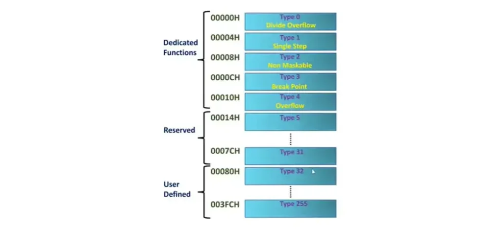
- In the 8086 Microprocessor Architecture, we have a total of 256 vector interrupts with well-defined vector locations.
- It can be executed by the Programmer using INT instruction.
Interrupt Vector Table In 8086 Microprocessor Architecture
Features of 8086 Microprocessor
- 8086 Microprocessor has 16 bits ALU, So the operating speed of 8086 Microprocessor has increased significantly well.
- It has 16 bits of data bus, so in one machine cycle, it can transfer 2 bytes.
- It has 20 bits of address lines.
- 8086 Microprocessor has two internal hardware units, the Bus Interface Unit and the Execution Unit. These units define the 8086 Microprocessor Architecture.
- This Microprocessor supports Pipelining, So Multiple instructions can be executed in Parallel to increase the Execution speed of the Microprocessor.
- It contains four 16-bit general-purpose registers(AX, BX, CX & DX). we can use it with 8 bits also. it also contains two 16-bit Index registers and stack pointers.
- 8086 Microprocessor supports the Memory segmentation.
- It contais16 bit flag registers.
- It has two hardware modes, maximum mode, and minimum mode.
- It provides memory banks.
- It has an upgraded instruction set and interrupt service.
Difference Between 8085 Microprocessor and 8086 Microprocessor
The comparison between 8085 and 8086 Microprocessors is given below:
| Features | 8085 Microprocessor | 8086 Microprocessor |
| Architecture | 8-bit Architecture | 16-bit Architecture |
| Data Bus Width | 8-bit | 8-bit |
| Address Bus Width | 16-bit | 20-bit |
| Registers | 74 Instructions, 74 Opcodes | 246 Instructions and 119 Opcodes |
| Clock Speed | Typically 3MHZ | Typically 5-10MHZ |
| Addressable Memory | 64KB | 1 MB (With Segmented Addressing) |
| Instruction Set | Simple and Smaller Instruction Set | Complex and Larger Instruction Set |
| Interrupts | 5 Maskable Interrupts | 256 Interrupts(Vectored and Non-Vectored) |
| Memory Segmentation | No Segmentation | Segmentation used for addressing |
| Stack Pointer | Single 16 bit Stack Pointer | Single 16-bit Stack Pointer |

