8051 Microcontroller Architecture with Pin Diagram and Applications
Introduction
A single-chip Microcontroller MCS-51, Commonly known as 8051 Microcontroller was developed by Intel in 1980. It is based on Harvard Architecture and principally used in embedded systems. John H. Wharton was the architect of the Intel MCS-51 Or 8051 Microcontroller. Primarily it was developed by using N-type metal-oxide-semiconductor(NMOS) technology, but later versions were based on Complementary metal-oxide-semiconductors(CMOS) technology. Such types of microcontrollers were best suitable for battery-powered devices as compared to their forerunners.
What is an 8051 Microcontroller?
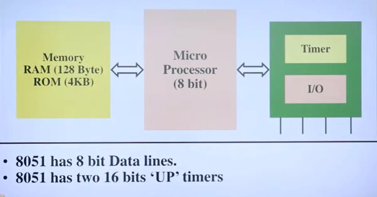
The 8051 Microcontroller was first introduced by Intel in 1981. It was a kind of integrated circuit that contained 40 pins along with DIP or Dual Inline Package, 128 bytes of RAM, 4kb ROM, and two 16-bit timers/counters. The 8051 Microcontroller also includes programmable as well as addressable 4-parallel 8-bit ports. The 8051 Microcontroller Architecture also has a system bus that plays an important role in connecting all devices to the CPU(Central Processing Unit). This bus includes an 8-bit data bus, a 16-bit address bus, and bus control signals as well. The 8051 Microcontroller also has two buses, one for programming and another for data. So it means it has two storage rooms for both data and programs. This microcontroller also consists of an 8-bit accumulator, 8-bit processing unit, and 8-bit register respectively.
8051 Microcontroller Architecture
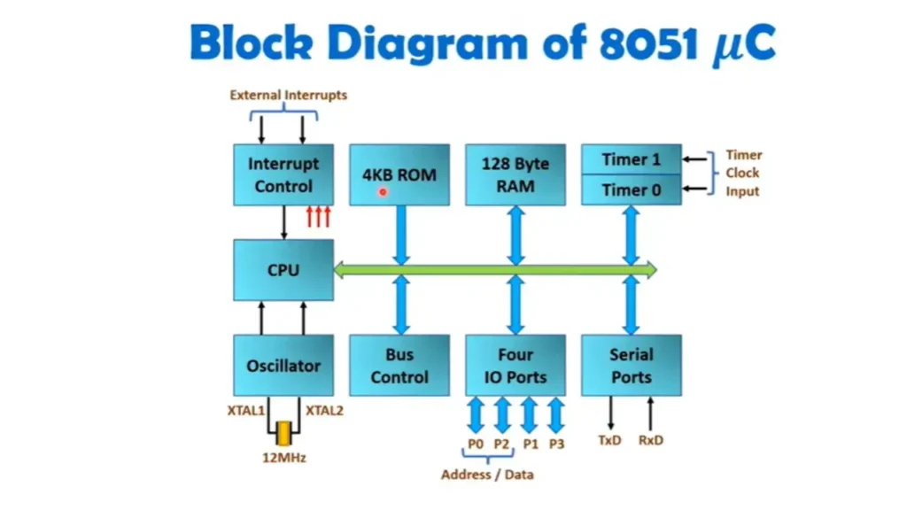
8051 Microcontroller follows Harvard Architecture. The 8051 Microcontroller architecture consists of CPU, Interrupts, oscillator, memory, registers, timers & counters, bus, data types, and stack, etc. All the essential components of the 8051 Microcontroller architecture are explained below one by one.
Pin Diagram of 8051 Microcontroller Architecture
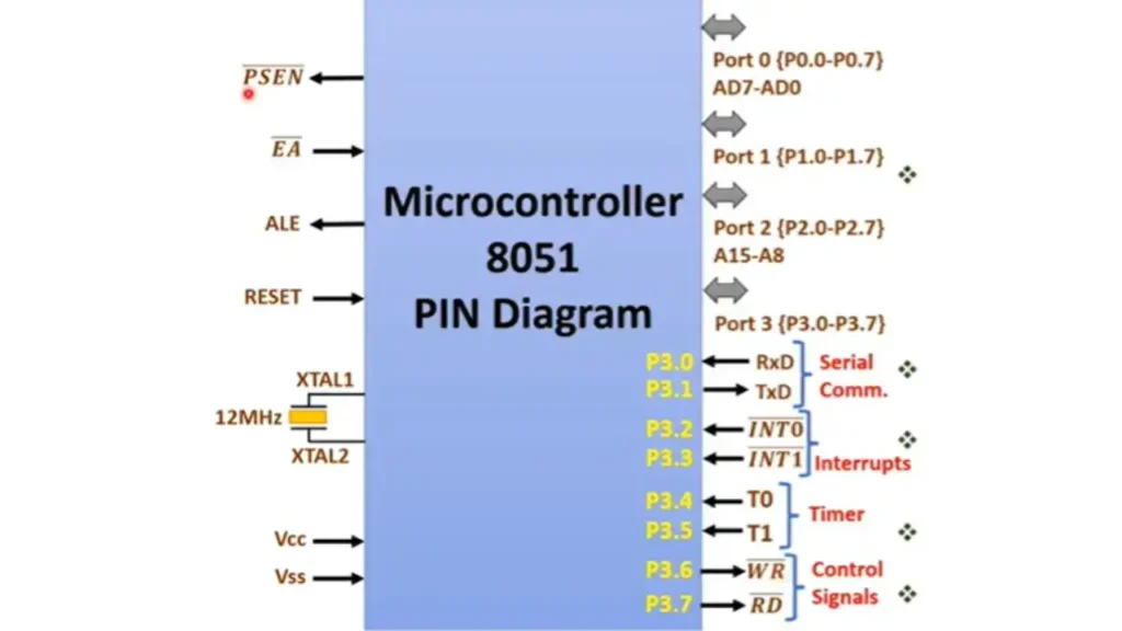
- Power Supply
- It has Vcc=+5V and Vss=Reference(Ground)
- XTAL1 and XTAL2
- Crystal is connected in between these two points. a 12 MHz crystal clock is provided. In serial communication, the operating frequency is chosen to be 11.0592MHz, to get started with universal baud rates.
- RESET
- It is used to RESET 8051 Microcontrollers. On a reset PC becomes 0000H, this address is called the RESET vector address. From this address, 8051 executes BIOS programs. The BIOS program is used to set up the system and make the system ready for the end user.
- ALE-Address Latch Enable
- It is used to separate Address and Data. In 8051, AD0-AD7 lines are time multiplexed. If ALE=1, BUS carries an address. If ALE=0, BUS carries data.
- EA-Enable External Access
- 8051 has an internal 4KB ROM. If EA=O, 8051 will discard the internal 4KB ROM and the external ROM memory location will start from 0000H. If EA=1, 8051 will consider an internal 4KB ROM with starting address 0000H to ending address 0FFFH, and the external ROM memory location will start from 10000H.
- PSEN-Program Status Enable
- 8051 Microcontroller has 16-bit address A0-A15. By that we can interface 64KB of external ROM and 64KB of external RAM, making it a total 128 KB memory space. Both have the same address range 000H to FFFH. PSEN reads data from external ROM. RD and WR are used for reading and writing external RAM. PSEN is referred to as program status enable, as it allows programs to be read from external ROM.
- Port0-(P0.0-P0.7)/AD-AD0
- On port 0, 8051 has 8-pins P0.0-P0.7 We can perform 8-bit operation on the entire port. We can also perform a 1-bit operation on port 0(like we can set bit, clear bit, and complement bit). Port 0 also carries time multiplexed address data lines AD7-AD0. So, it holds the A7-A0 address when ALE=1 and D7-D0 when ALE=0. For memory access, 1st address will be given then data will be given on these lines.
- Port 1-(P1.0-P1.7)
- On port 1, 8051 has 8-pins P1.0-P1.7, and we can perform 8-bit operation on the entire port. We can also perform a 1-bit operation on port 1(like can set bit, clear bit, and complement bit). Port 1 has no other alternate functions.
- Port 2-(P2.0-P2.7)/A15-A8
- On port 2, 8051 has 8-pins P2.0-p2.7, and we can perform 8-bit operations on the entire port. We can also perform a 1-bit operation on port 2(like we can set bit, clear bit, and complement bit). Port 2 also carries address lines A15-A8.
- Port 3-(P3.0-P3.7)
- On port 3, 8051 Microcontroller has 8-pins P3.0-P3.7, and we can perform 8-bit operation on the entire port. We can also perform 8-bits operation on the entire port. We can also perform 1-bit operation on port 3( like we can set bit, clear bit and complement bit). Port 3 also have many alternate functions.
- RxD(P3.0) & TxD(P3.3)
- RxD and Txd Pins are used for serial communication.
- INT0(P3.2) and INT1(P3.3)
- They are hardware interrupts of the 8051 Microcontroller, in which INT0 has higher priority.
- T0(P3.4) and T1(P3.5)
- These are the timer clock input of 8051.
- WR(P3.6) and RD(P3.7) Control Signals
- These pins are used for read and write operations for RAM.
Block Diagram of 8051 Microcontroller
Internal RAM Structure in 8051 Microcontroller
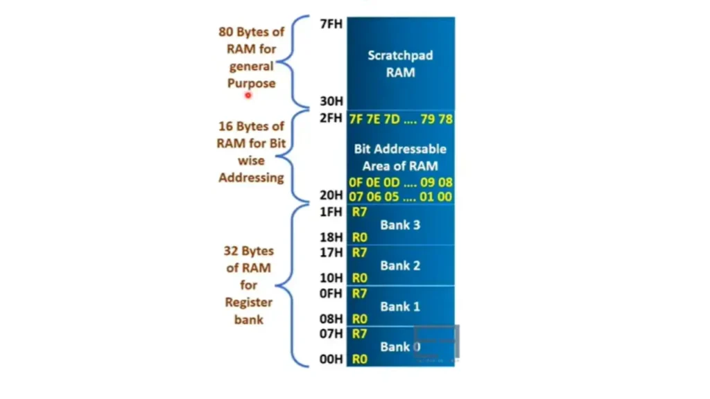
8051 Microcontroller has four register banks and each register bank has eight registers R0-R7. The selection of register banks can be done by two bits of PSW Register, by PSW.3 and PSW.4, we can select any register bank.
CLR PSW.4
SETB PSW.3 ; Here RS=O1 means bank 1 is selected.
RAM address 00H to 1FH holds four register banks.
MOV A, RO ; Copy R0 into A
MOV A, 08H ; Copy R0 of Register bank 1 into A
8051 Microcontroller Bit Addressable Area in RAM.
16-bytes of RAM from 20H to 2FH holds bit addressable area in internal RAM of 8051 Microcontroller.
16×8=128 Addressable bits in the area.
These bits are addressed as per 00H to 7FH, in total 128 bits. These locations can have bit as well byte wise operations.
SETB 7FH ; Set MSB of 2FH RAM location.
CLR 08H ; Clear LSB of 21H RAM location.
MOV 20H, #FFH ; Set all bits of 20H RAM locations.
General Purpose Area in RAM(Scratchpad RAM)
80 byte of RAM from 30H to 7FH holds general purpose area in internal RAM of 8051 Microcontroller. It can be used for general purpose operations.
SFRs of 8051 Microcontroller
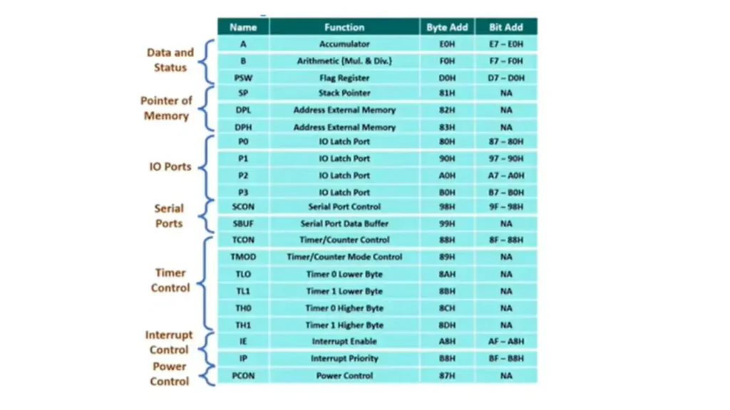
SFR is a special function register having an 8-bit size. These are on-chip registers for special functions of 8051(Timers, Counter, IO, Serial Communication, Interrupt, Power Saving Modes, etc.). There are 21 SF Registers with 8051, which are used with their addresses in instructions to reduce the number of opcodes in 8051. We have seen that internal RAM is used with addressing from 00H to 7FH, Likewise, SFRs are used with addressing in between 80H to FFH. This addressing supports byte and bit-wise operations. This addressing reduces the number of opcodes for total instructions.
SETB P0.0 ; SETB has opcode & P0.0 has address 80H
8051 Supports bit-wise special functions and byte-wise special functions if addressing is not done with SFRs, then there would be too many opcodes and that will make too much complicated instruction decode circuit.
Editor, Compiler, Assembler, Linker & Loader

In editor we write programs for Microcontroller and the programs may be written in Assembly language or Higher Level language(C Language). By writing programs we generate source files.
Assembler & Compiler
They are used to convert Assembly language into machine code or object file. They also show errors if any syntax error is there in the program. Compiler also shows warnings if found there.
Linker
It links all the object files of the compiler and assembler with the use of libraries. It generates the executable files.
Loader
Loader is used to load executable files into the memory of microcontrollers. Once a program is loaded into memory, the microcontroller can execute it as per the requirement of the user.
Data Types of 8051 Microcontroller
It supports Binary, Decimal and Hexadecimal data formats. For example
MOV A, #00110110 B ; A—00110110, Binary 00110110 is loaded in A which is equivalent to 36H.
MOV A, #15 ; A—15, Decimal 15 is loaded in A which is equivalent to 0FH.
MOV A, #15H ; A—15H, Hexadecimal 15H is loaded in A.
Assembler Directives of 8051 Microcontroller
Assembler directives are also referred to as pseudo opcodes. They are not instructions so they are not executed by MPU. It is used to give directions to assemblers. ORG(Origin), ORG 1000H, ORG Directive is used to indicate the beginning address. After writing ORG 1000H, program or data will be stored at 1000H Memory location. Some assemblers may use .ORG, so you need to check that as well. If you don’t write “H” after the number then it will consider the decimal address with ORG.
End Assembler Directives of 8051 Microcontroller
End(Terminate)
It is used to END source file{.asm file}. Anything after the END directive will be ignored by the assembler.
EQU(Equate)
It is used to define a constant without occupying a memory location. It is used for constant values in a program.
DB(Define Byte)
It is used to define byte data.
Here , 8-bits(bytes) numbers can be decimal, hexadecimal, Binary or ASCII numbers.
ORG 1000H
Data 1: DB 25 ; data 1 is defined by 25 decimal numbers.
Data 2: DB 25H ; data 2 is defined by 25H Hex number.
Data 3: DB 00110011 B ; data 3 is defined by 33H Binary number..
Data 4: DB ‘A’ ; data 4 is defined by ASCII of A.
Data 5: DB “EF” ; data 5 is defined by String of ASCII.
IO Ports of 8051 Microcontroller Architecture
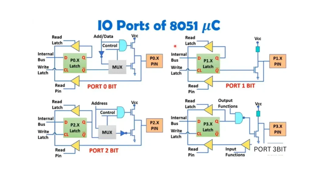
Important Parts or Components of 8051 Microcontroller
PSWFlag Registers in 8051 Microcontroller
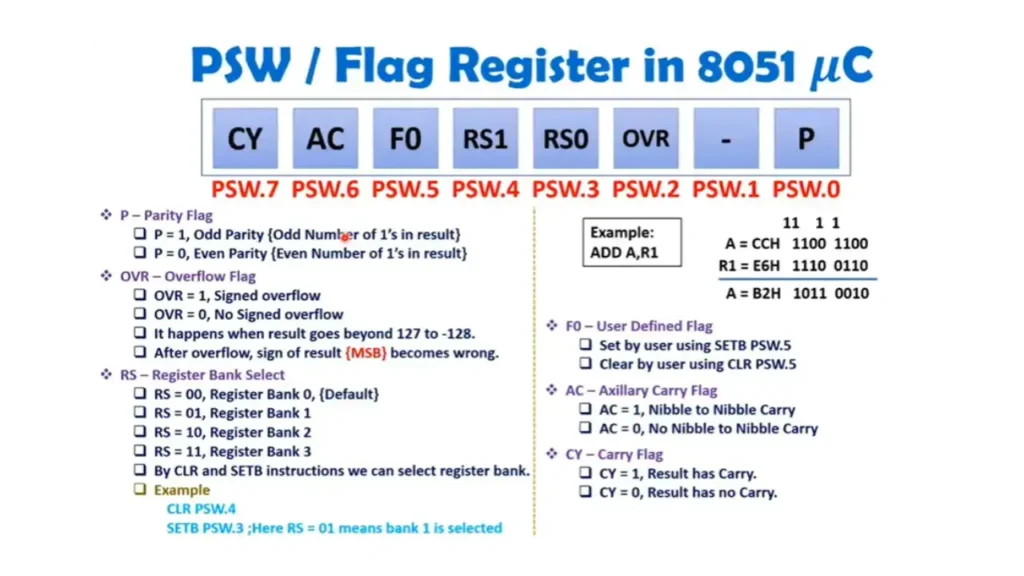
PSW-Program Status Word
It is an 8-bit register and it is also called Flag Register. It gives status after every instruction execution in the program. The flags can also be changed by programmers. PSW is a bit addressable register.
PSW/Flag Registers in 8051 Microcontroller
P-Parity Flag
- P=1, Odd parity( Odd number of 1’s in the result).
- P=0, Even Parity (Even number of 1’s in the result).
Overflow Flag-OVR
- OVR=1, Signed Overflow.
- OVR=0, No Signed Overflow. It happens when the result goes beyond 127 to 128. After overflow, the sign of result(MSB) becomes wrong.
Register Bank Select-RS
- RS=OO, Register Bank o, (Default).
- RS=O1, Register Bank 1
- RS=1O, Register Bank 2
- RS=11, Register Bank 3
- By CLR and SETB instructions we can select register bank.
User Defined Flag-F0
- It can be set by user using SETB PSW.5 and also clear by user using CLR PSW.5
Auxiliary Carry Flag-AC
- AC=1, Nibble to Nibble Carry.
- AC=0, No Nibble to Nibble Carry.
Carry Flag-CY
- CY=1, Result has carry.
- CY=0, Result has no carry.
ROM Organization in 8051 Microcontroller
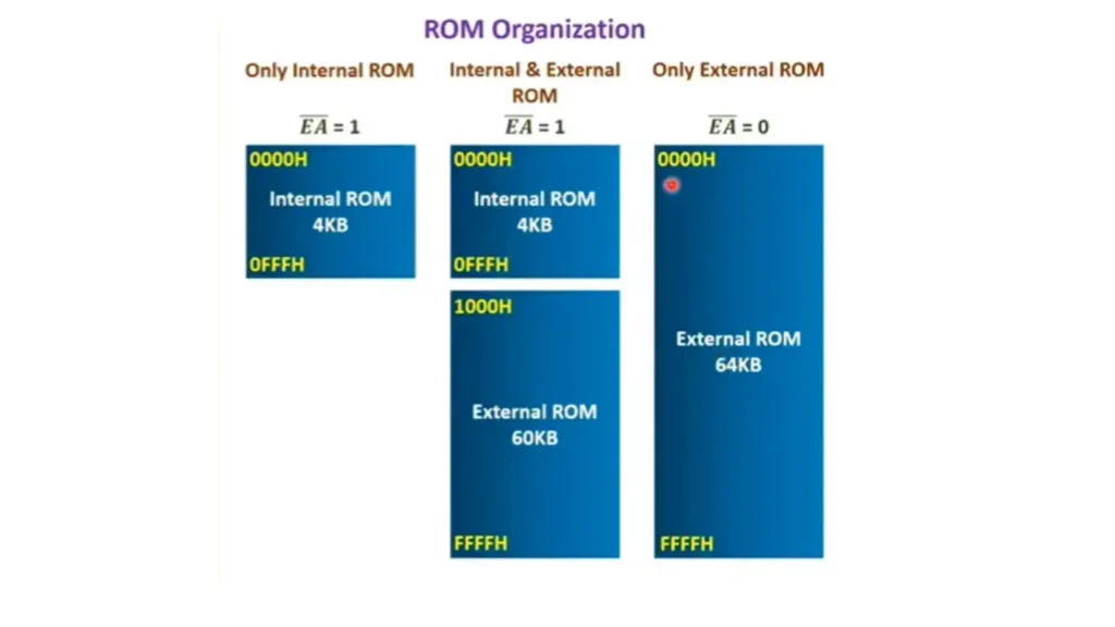
8051 Microcontrollers have four different memories.
- Internal ROM(4KB)
- Internal RAM(128 Bytes)
- External ROM(Max 64KB)
- External RAM(Max 64KB)
ALU(Arithmetic Logic Unit)
It performs 8-bit arithmetic and logic operations. It can also perform one bit operations.
Accumulator A
Accumulator is an 8-bit register. Most arithmetic and logical operations are performed with respect to the accumulator.
Register B
It is an 8-bit register. It is dedicated to multiplication and division.
PC-Program Counter
It is a 16-bit register. It holds the address of next instruction in program memory of ROM. The PC gets incremented automatically as soon as any instruction is fetched. In the case of a branch, a new address is loaded on the PC.
Data Pointer(DPRT)
It is a 16-bit register that holds the address of data in memory of RAM. Data pointer is further divided into two registers of 8-bits(DPH- Higher Byte and DPL-Lower Byte). It is used by programmers to transfer data from external RAM. It can also be used as a pointer for a look up table in ROM, using indexed addressing mode.
Stack of 8051 Microcontroller
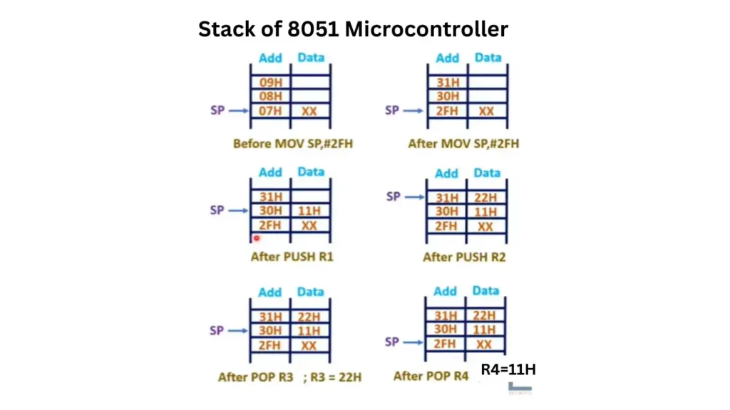
Stack Pointer is an 8-bit register and it holds the address at the top of stack. The stack is present in internal RAM and internal RAM address is from 00H to 7FH. It is used for PUSH and POP instructions. On RESET, Stack Pointer of 8051 indicates 07H address of internal RAM.
Features of 8051 Microcontroller Architecture
The key features of 8051 Microcontroller architecture are explained below.
| Sr# | Features | Description |
|---|---|---|
| 1 | Architecture | 8-bit Microcontroller |
| 2 | ALU and Accumulator | 8-bit ALU and Accumulator |
| 3 | Registers | 8-bit registers, including 16-bit register |
| 4 | Data Bus | 8-bit data bus |
| 5 | Address Buses | Dual 16-bit address bus |
| 6 | Program Counter(PC) | 16-bit program counter |
| 7 | Data Pointer(DPTR) | Data pointer with 8/11/16-bit operations |
| 8 | Boolean Processor | 1-bit accumulator, 32 registers(4×8-bit) |
| 9 | RAM | 128 or 256 bytes on-chip RAM(IRAM) |
| 10 | ROM | Dual 16-bit address bus for 64KB ROM |
| 11 | on-Chip ROM | Included(ont on 803x variants) |
| 12 | Register Banks | Four fast switchable register banks |
| 13 | Interrupts | Have Two external and three internal interrupts |
| 14 | Special Functions Registers(SFRs) | 128-bytes controlling peripherals |
| 15 | I/O Ports | Four 8-bit bi-directional Input/Output ports |
| 16 | UART(Serial Port) | Included |
| 17 | Timers | Two 16-bit timers/counters |
| 18 | Power Saving Mode | Available on some derivatives |
| 19 | CPU | 8-bit CPU having two registers A and B |
| 20 | Internal ROM | 8K bytes and flash memory for programming |
| 21 | Internal RAM | 256 bytes, including general purpose and SFRs |
| 22 | Oscillator and CLK Circuit | Included |
| 23 | Control Registers | PCON, SCON, TMOD, TCON, IE, IP, T0 and T1 |
| 24 | Stack Pointer(SP) | 8-bit |
| 25 | Processor Status Word(PSW) | Included |
| 26 | Processor Status Word(PSW) | Included |
| 27 | I/O Pins | 32-Pins and are arranged in four ports(P0,P1,P2,P3) |
| 28 | Serial Data Tx & Rx | Full-Duplex Operation |
Uses of 8051 Microcontroller
8051 Microcontrollers are being used in different fields and some of thme are given below.
Applications of 8051 Microcontroller Architecture
Microcontroller is used in many embedded system applications such as remote control, microwave oven, washing machine, etc.
Once a controller is embedded in an application, the program of the controller should be fixed and it should be stored in ROM.
Data may change in application, like time, and temperature and it will be stored in RAM.
Fixed data will be stored in RAM as a lookup table(ASCII, SSD, etc).

